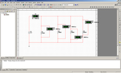
Activity 1.2.3
In this project we were using computer programs to calculate various values of circuits.
1. It should be obvious that using a CDS to analyze circuits is far easier than performing the calculations by hand. Yet, being able to perform these calculations by hand is still an important skill for a circuit designer. Why?
Engineers do not always have access to cds to do the calculations. Its important to do your own calculations to check the computer and verify your work.
2. Using the results from step (3) of the procedure, verify Kirchhoff’s Voltage Law.
2.02+2.47+.81+2.02=7.32
3.Using the results from step (5) of the procedure, verify Kirchhoff’s Current Law.
.200+.200+.200=6.00
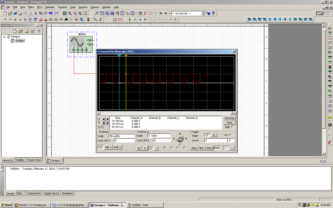
Activity 1.2.5
This project introduced students to the basic uses of the oscilloscope in CDS
1. List the characteristic that makes a digital signal different from an analog signal.
Digital signals are less precise and drop below zero on graphs. Analog signals are very accurate and don't go below zero on graphs.
2.In the diagram shown below, label the parts of the analog signal.
A-Amplitude (Peak)
B-Amplitude (peak)
C- Period
3. In the diagram shown below, label the parts of the digital signal.
A-Amplitude
B-Time high
C-Period t
D-Time low
E-Rising edge
F-Falling edge
4.What are the two standard voltage levels that are acceptable for a digital signal?
0 to 5 volts
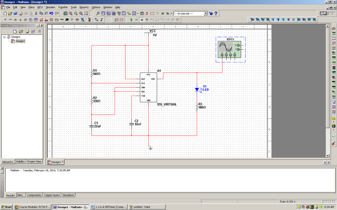
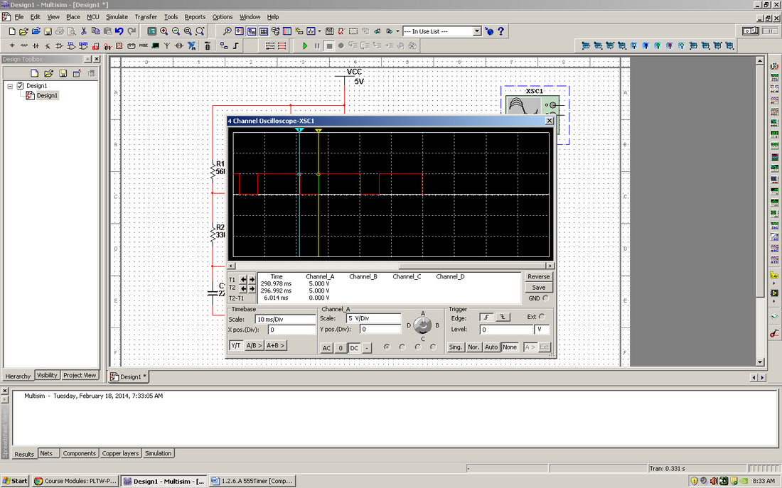
Activity 1.2.6
1. Review the results of the data collected in step (3) of the procedure.
· What effect did varying the RA have on the frequency and duty cycle?
The lower the RA the higher the frequency and the duty cycle.
· What effect did varying the RB have on the frequency and duty cycle?
It had a similar effect but it made the values even lower.
· What effect did varying the C have on the frequency and duty cycle?
IT made the duty cycle very low and similar to each other.
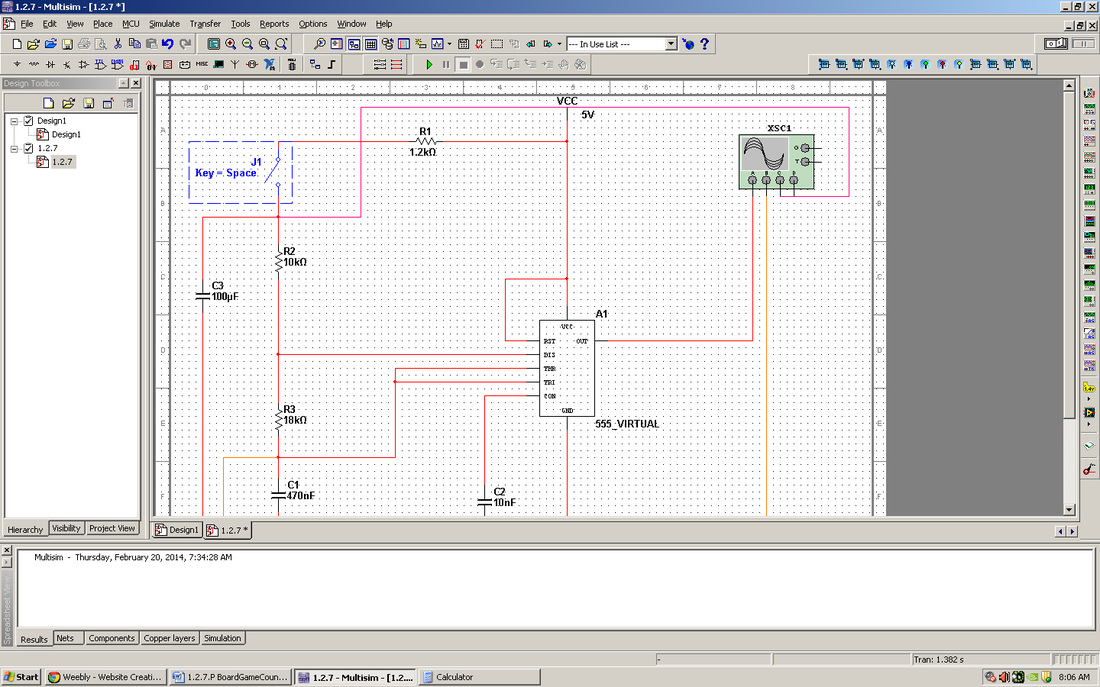
Activity 1.2.7
1. When
you press the push button of the Board Game Counter, the 555 Timer oscillates
at approximately 65 Hz. It you want the oscillation to start at 100Hz, what
value would you apply to C2?
You would apply 100 micro farads.
2. The values of R8 & C1 determine the time from when the push button is released to when the oscillation stops. If you wanted to lengthen this time period, what changes would you make to one or both of these components? Explain.
You would increase the resistance of R8. This would decrease the amount of electricity flowing through components.
Activity 1.3.1
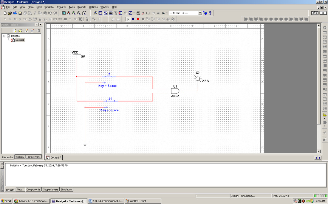
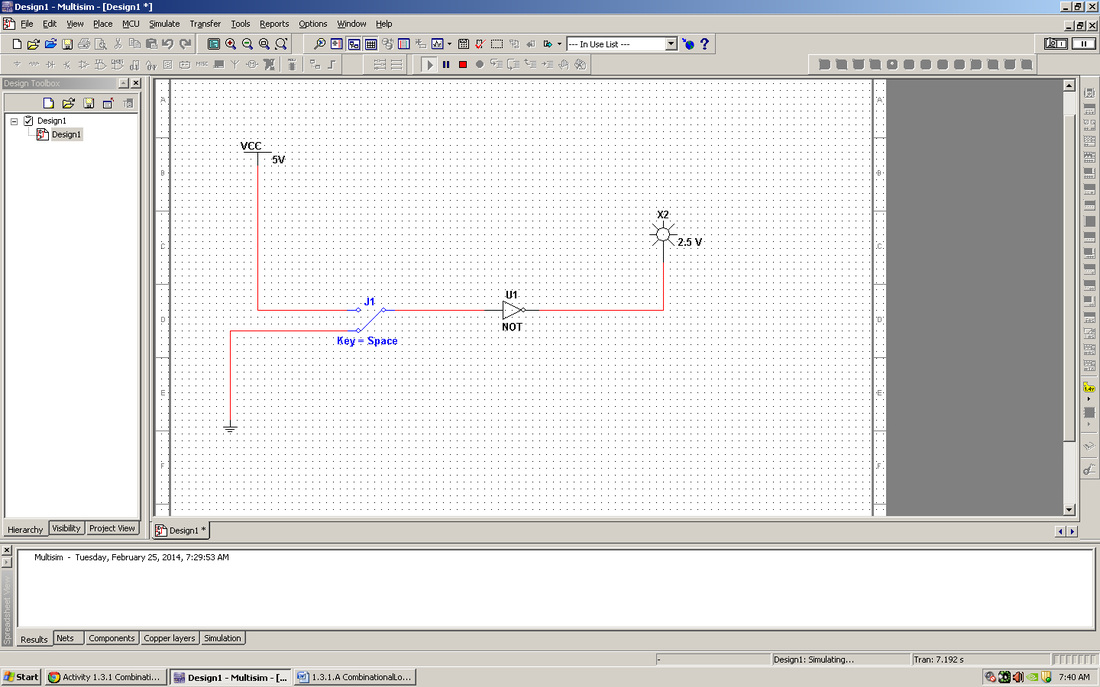
1. From your life experiences, list 3-5 examples of products that you have used that contain combinational logic.
Car safety systems, strobe lights, and Buses.
2. Throughout this activity we used switches for the circuit inputs and a probe for the circuit outputs. Though this works fine for testing purposes, it is not practical for real-world applications of combinational logic circuits. List three input and three output devices that would be used with real world applications of combinational logic.
LED's, Speakers, and seven segment displays.
Push button switches, light switches, and SPDT
Activity 1.3.2
1. List 3-5 real-world applications where you might find counters like the one examined in this activity.
Laser pointer and led pens, computer alert signals, and car engine signals
2. Simple counters are just one application of sequential logic. From your life experiences, list 3-5 examples of products that you have used that contain sequential logic.
Game systems, digital sudoku games, and applications on phones.
Activity 1.3.3
1. The combinational logic in Board Game Counter was AOI logic. What are three gates that are used to implement AOI logic?
And or and Not gates.
2. On the 74LS74 D flip-flop, the CLK input has a small triangle. The PR (preset) and CLR (clear) inputs have a circle. What do these symbols mean?
The places to add inputs to the device.
3. What is the primary characteristic that differentiates combinational and sequential logic?
Combinational uses multiple gates at the same time to create the desired effect, while sequential uses one.
Activity 1.3.4
1. Using the datasheet obtained for the 74LS04 Hex Inverter Gates as a reference, answer the following questions:
· What is the nominal Supply Voltage (Vcc)?
4.17 min
· What is the maximum Free Air Operating Temperature (TA)?
70 max
· What is the typical LOW-to-HIGH Propagation Delay (TPLH)?
7
· What is the typical distance between two adjacent pins on a 14-Pin Dual-In-Line IC Package?
less than an inch
3. Who is Jack Kilby? What was his contribution to the field of digital electronics?
He is the man who invented data sheets.
1. Likewise, in the purpose section, you were asked;
(i) What is the function of a MAN6760,
(ii) How many pins does an LM555 time have, and
(iii) What is the maximum supply voltage for a 74LS08.
Answer the questions below.
· MAN6760 Its used to increase the productivity of a circut
· LM555 24 pins
74LS08 5.25 units
Activity 2.1.3
1. A digital logic circuit with (2) inputs has (4) input combinations. One with (3) inputs has (8) combinations. One with (4) inputs has (16) combinations.
2. How many input combinations would a digital logic circuit have if it has (5) inputs? How about (6) input?
10 combonations and 12 combonations
3. Mathematically express the relationship between the number of input (N) and the number of input combinations (C).
The C is twice the N
4. Write the un-simplified logic expression for the truth table shown below.
Activity 2.1.4
Conclusion
1. In your own words, describe the process used to analyze a logic circuit where you first extract a truth table and then derive the logic expression.
test each input and create a truth table from result
2. Again, in your own words, describe the process used to analyze a logic circuit where you first extract the logic expression and then derive the truth table.
use the given inputs and create a truth table from the results
3. Did you find one of the processes easier than the other? Which one and why?
the first because you already have the results
4. How can two logic equations be equal or equivalent?
by having the same truth table
Activity 2.1.5
F2 – CDS
Conclusion
1. The two circuits shown below are equivalent, meaning that they both produce the same output, Minterm=WXYZ.
Analyze each circuit to prove that they both produce the output Minterm=WXYZ.
Since the two versions produce the same output and require the same number of gates to implement, is one version any better than the other?
Note: Think delays. Though we don’t normally worry about it in our designs, remember that all logic gates have propagation delay.
2. Shown below are two equivalent circuits. One was implemented from an SOP logic expression and the other from the equivalent POS form.
First analyze the SOP version to determine the logic expression for F3 in SOP form. Use this expression to generate a truth table for the circuit.
Now analyze the POS version to determine the logic expression for F3 in POS form. Use this expression to generate a truth table for the circuit.
How do the two truth tables compare? Is the column for F3 the same for both? They should be. If they are not the same, review your work and make any necessary corrections.
Since the truth tables are the same for F3, what could be said about the two logic expressions?
Activity 2.1.6
1. Describe the process that you would use to simplify a logic expression using Boolean algebra.
Apply various theorems to take away like terms and simplify the expression.
2. How do you know when you are finished simplifying and have arrived at the simplest equation?
The equation wont simplify anymore than it has
3. Other than using Boolean algebra, how could you prove that two circuits are equivalent?
When two circuits have the same truth tables
4. If you worked for a company that manufactured the coffee vending machine that used the poorly designed circuit, how much money would your new design save the company annually if each GATE cost 15¢ and the company made 500,000 vending machines per year.
30,000$
As an experienced engineer, you earn $75 per hour. The total redesign took you two hours (including a coffee break). What would the company’s Return-On-Investment (ROI) be on your time?
Was it a good investment?
Yes it was a good investment.
Activity 2.1.7

1. Draw the gate equivalent for DeMorgan’s two theorems.
-x+-y and -x -y
2. How would you prove that the original Do-Nothing circuit and the simplified version are equivalent?
By comparing the two truth tables
Your company was SO pleased with the money you saved them on the coffee vending machine project (last activity) that they’ve promoted you to VP of engineering and given you a raise to $100 per hour. Congratulations.
Your first decision as VP is to start manufacturing the simplified version of the Do-Nothing circuit. (Did we mention that the circuit doesn’t do anything?)
3. If each GATE cost 20¢ and you made 100,000 units, how much of the company’s money did you waste on your first project?
10,000 dolars
Did you get fired? No I got promoted again
activity 2.2.3
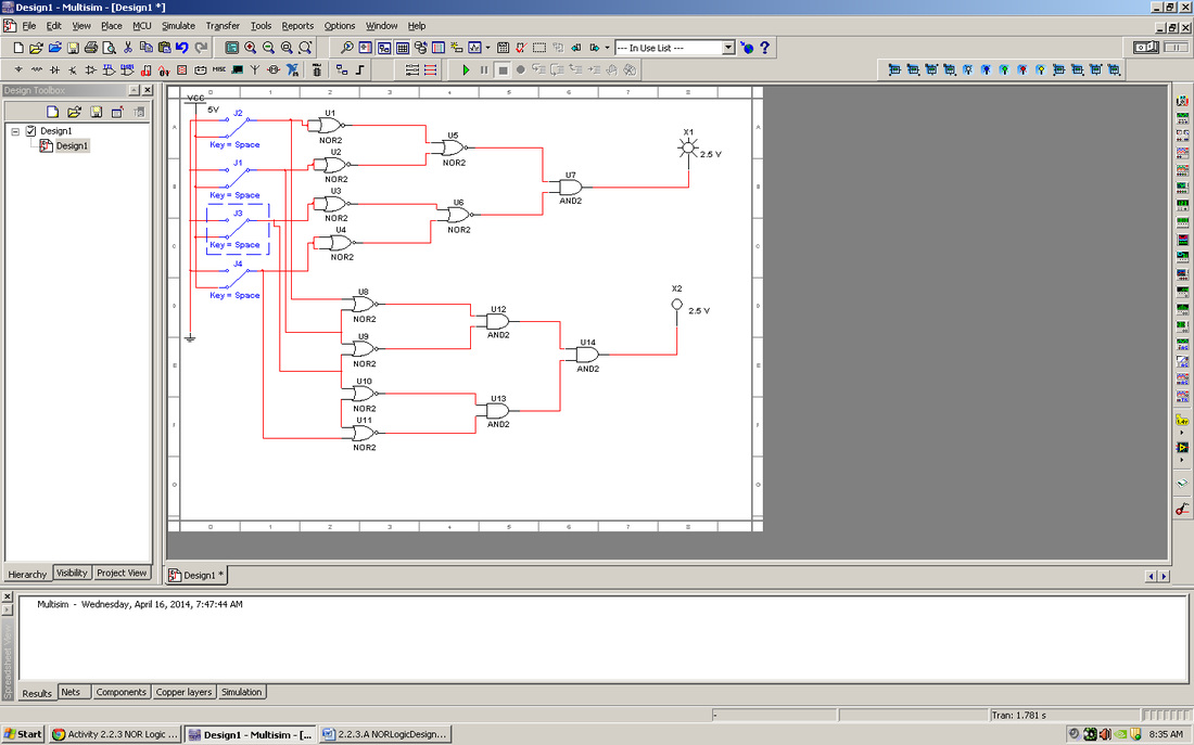
1. For your NOR implementations, how many ICs (i.e., 74LS02 chips) were required to implement your circuits? Again, we are counting ICs, not gates.
3 gates were used
2. In terms of hardware efficiency, how does the NOR implementation compare to the AOI implementation (Refer to Activity 2.2.3 NAND Logic Design)?
It is more efficient than aoi but not by much
3. In terms of hardware efficiency, how does the NOR implementation compare to the NAND implementation in Activity 2.2.3 NAND Logic Design?
It is slightley less efficent than NOR
NOR gates are available with three inputs (74LS27). Could this chip have been used for this design? If so, how would it have affected the efficiency of the design?
Yes it would work more efficentley
Kmapping
- Give three advantages of using K-mapping to simplify logic expressions over Boolean algebra.
- Its faster than boolean simplifiication it helps orginazie information and it provides a visual
- The three variable K-maps shown below can be completed with three groups of two. The two groups shown (cells #1 & #3; cells #4 & #6) are required. The third group, needed to cover the one in cell #2, could be cells #2 & #3 or cells #2 & #6.
Write the two possible logic expressions for the function F1.
-ac or a-c
These logic expressions are considered to be equivalent (not equal). Explain what this means.
they produce the same truth table
Activity 2.2.4
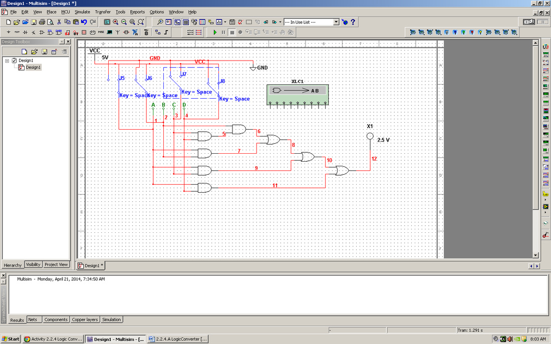
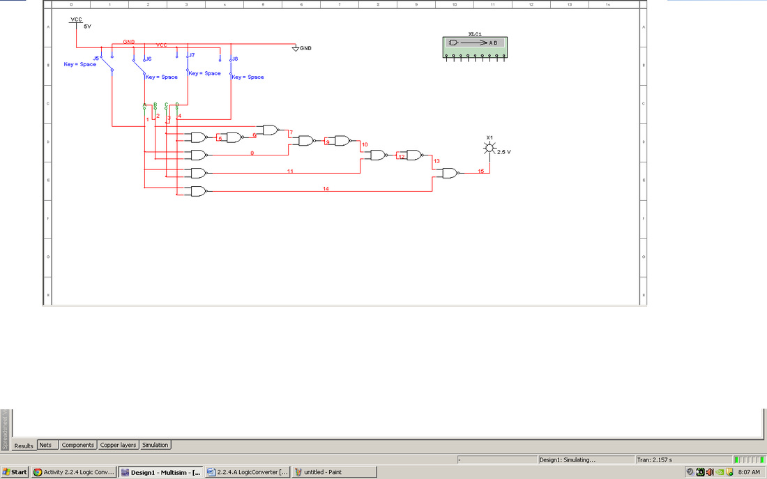
1. How did the AOI implementation of the Majority Vote – Voting Machine created by the Logic Converter compare to the design that you completed manually in the previous lesson?
The circuits were similar but the computer generated circuit was larger and less efficient that the one that i made.
2. In terms of hardware efficiency, how does the NAND Only implementation compare to the AOI implementation?
The NAND is actually less efficent than the AOI implementaion
3.Though the logic converter is a very powerful tool, it does have some limitations. What are these limitations?
The circut can only work in one direction or in one way
Activity 2.3.1
What do alarm clocks, cable TV converter boxes, home answering machines, and inexpensive calculators all have in common? In addition to being built from electronics, many also include seven-segment displays as part of their design.
There are two types of seven-segment displays, common cathode and common anode. Understanding how these displays work and the differences between them is fundamental to designing many different types of electronic devices.
In this activity you will learn how to use seven-segment displays to display both alpha and numeric characters.
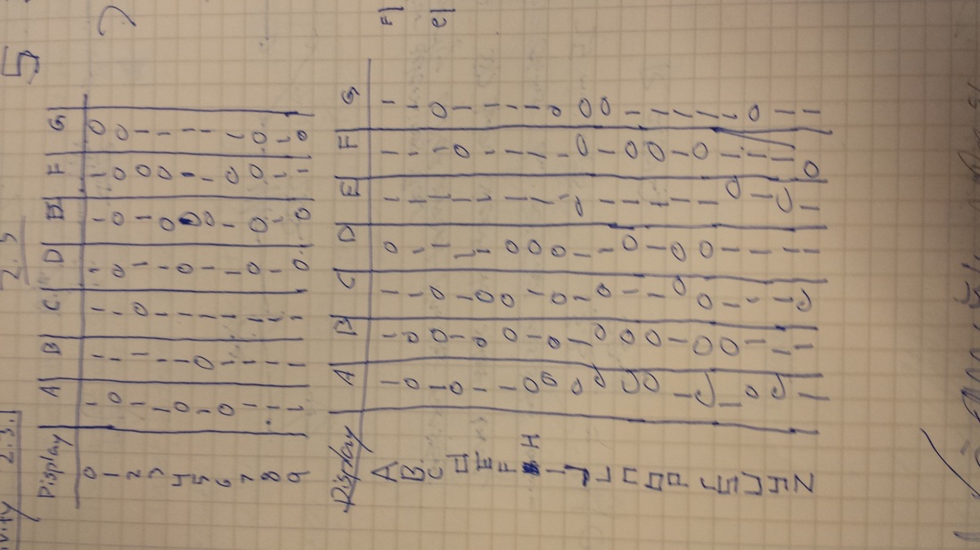
1. Complete the wiring of the seven-segment displays shown below so that they will display your age. If you are 15, display a (1) on the common cathode display and a (5) on the common anode display.
Completed in multisim
Common Anode
Common Cathode
2. List five words of three characters or more that you could spell out using a seven-segment display. Don’t forget about lower case characters. Be creative. Be polite.
· CLOSE
· PAUSE
· HELLO
· SHUFFLE
PLAY
Completed in multisim
Common Anode
Common Cathode
2. List five words of three characters or more that you could spell out using a seven-segment display. Don’t forget about lower case characters. Be creative. Be polite.
· CLOSE
· PAUSE
· HELLO
· SHUFFLE
PLAY
