Project 1.2.4 conclusions
1. You have now analyzed the same circuits three times;
a. by hand in Activity 1.2.2
b. via simulation in Activity 1.2.3
c. via breadboarding in this activity
How did these values compare and what might account for any differences?All of the values were rather similar and comparable while a few were off by a few decimals. The exactness of the operator accounts for the variety in answers.
2. How does the technique for measuring current with a DMM differ from measuring voltage?
When measuring current the DMM has to be of the circuit while when measuring voltage the DMM just has to make contact
3. What is the origin of the name “breadboard”?
The first bread boards were copper wire nailed to bread cutting boards.
Project 2.1.1
Dear grandma,
How are you? I've been busy. I fixed that voting system you hated. It took alot of work but i did it. I designed it so there was an electronic way to count the majority vote. It wasnt that bad. I used two magical chips to help make this work. It wasnt that bad to make just a little trial and error.
Yours truley
TJ
Project 2.2.5
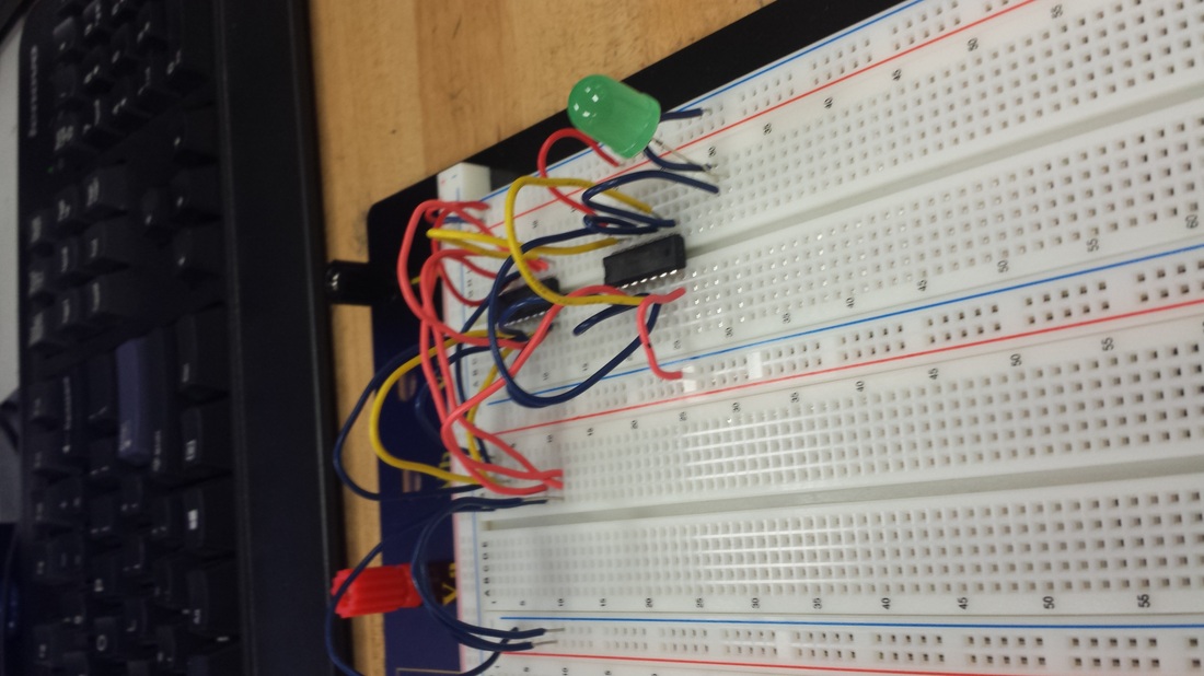
The acme fireplace company has asked us to design a circut that works when 3 of four sensors are emiting fire and outputs a 1 when there is a disagreem
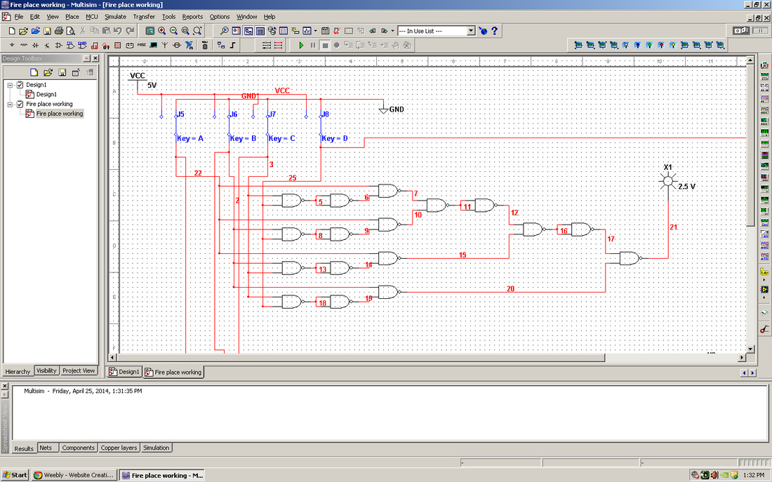
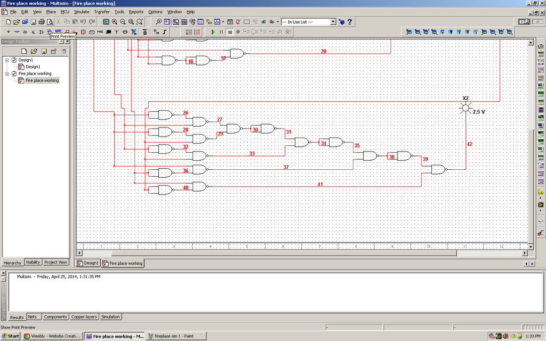
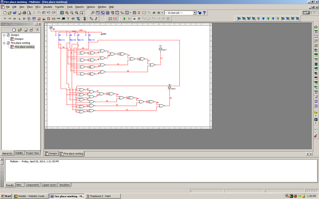
Using your engineering notebook/portfolio as a guide, write a conclusion (minimum 250 words) that describes the process that you used to design, simulate, and build your Fireplace Control Circuit. This conclusion must include all of your design work (i.e., truth table, K-Maps, etc.), preliminary and final schematics, parts list, and a digital photograph of your final circuit. The documentation should be complete enough that a student with a similar knowledge of digital electronics could reproduce your design without any additional assistance
I designed the circuit for the 2 parts of the fireplace separately and then i put the two together to make on full circuit. When i put the two togther i put them on a breadboard to make it work with the appropriate number of chips.
I designed the circuit for the 2 parts of the fireplace separately and then i put the two together to make on full circuit. When i put the two togther i put them on a breadboard to make it work with the appropriate number of chips.
project 2.3.2
In your digital electronics class of 20, there is a 6.8% probability that two of you share the same date of birth. This is assuming that you are all the same year level (sophomore/junior). If you are not, the probability would be even lower.
Your date of birth makes you unique. We are going to use this uniqueness to design a circuit that will display your date of birth on a single seven-segment display. Admittedly, this design does not have any real practical application, but is a fun exercise that will bring together all of the design techniques that you have learned in this lesson.
Your date of birth may make you unique in your class, but in 2006 there were 263,898,574,096 births world-wide. This means that on a daily basis, over 700,000,000 individuals share the same date of birth.
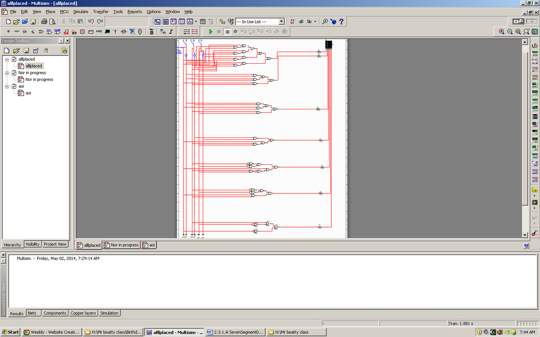
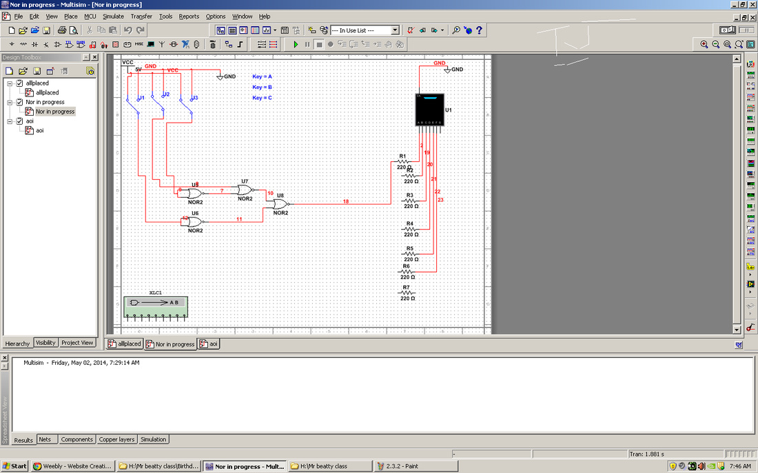
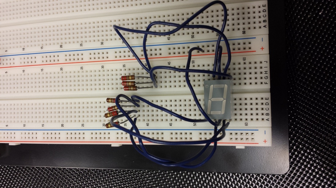
Using your engineering notebook/portfolio as a guide, write a conclusion (minimum 250 words) that describes the process that you used to design, simulate, and build your Date of Birth circuit. This conclusion must include all of your design work (i.e., truth table, K-Maps, etc), preliminary and final schematics, parts list, and a digital photograph of your final circuit. The documentation should be complete enough that another student with the same knowledge of digital electronics could reproduce your design without any additional assistance.
To design and produce my circuit I made a truth table to help me create the days and correct information to light up the SSD. Then I put that information into the logic converter on multisim to create the most efficient possible circuit i could. I then produced the circuit on the bread board having to start over multiple times my circuit becoming neater each and every time I did.
